Real-Time Embedded GUI Rendering — Deterministic Frames, No Dropped Updates

Real-time rendering in embedded GUI means every frame completes within a fixed deadline — no dropped frames on animated gauges, no latency on touch response, no jitter on live data updates. Sparklet achieves this through dirty-region rendering that skips unchanged screen areas, partial buffer mode that reduces RAM requirements, interrupt-driven input processing, and a frame scheduler that prioritises work within a tight budget.

How Does Real-Time Rendering Work in Embedded GUI?

Real-time rendering in embedded GUI means the display refresh cycle completes within a fixed frame deadline — typically 16.7 ms for 60 fps or 33.3 ms for 30 fps — regardless of UI complexity. No dropped frames. No variable latency on touch response. No rendering jitter on animated gauges or live data fields.

Achieving this on embedded hardware is not simply a matter of having a fast CPU. The rendering workload must be bounded: the worst-case pixel operations for any given frame must fit within the frame budget with headroom remaining for application logic, communication stacks, and RTOS tasks.

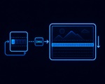
Sparklet's real-time rendering capability rests on four mechanisms: dirty-region rendering (skip unchanged pixels), partial buffer mode (reduce RAM, enable progressive flush), interrupt-driven input (zero-latency event capture), and a deterministic frame pipeline (input → state machine → dirty region → render → flush, in fixed order every frame). Together these ensure that per-frame work scales with the amount of UI activity — not with total screen area. Rendering engine architecture overview →

Four Mechanisms That Guarantee Real-Time Performance

Dirty-Region Rendering

The most effective optimisation in Sparklet's real-time pipeline is dirty-region rendering — restricting per-frame pixel operations to only the screen areas that have actually changed since the last rendered frame.

Every Sparklet widget maintains a dirty flag. When a widget property changes — a gauge value updates, a button transitions from normal to pressed, an animation frame advances — the widget sets its dirty flag and records its bounding rectangle as requiring repaint. Property changes that do not affect visual output (e.g., setting a value to the same value it already holds) do not set the dirty flag.

Before each render frame, the GDI layer collects all dirty bounding rectangles from the widget tree and merges overlapping regions into a minimal union. Only pixels within this union are recomputed. On typical industrial HMI screens — static background, a few live data fields — 80–95% of the screen area is skipped every frame. On a WVGA display at 60 fps, this represents approximately 1.8 billion pixel operations per second avoided.

Dirty-region rendering also benefits hardware-accelerated configurations. Even with DMA2D or D/AVE2D available, initiating an accelerator transfer for unchanged regions consumes DMA bandwidth. Skipping those regions frees the bus for concurrent SPI communication or ADC sampling. Rendering engine overview →

Partial Buffer Mode

Standard double-buffered rendering requires two full-screen framebuffers: one displayed by the LCD controller while the other is rendered into. On a WVGA (800×480) display at 16-bit colour depth, each framebuffer occupies 768 KB — two framebuffers consume 1.5 MB, more RAM than many MCUs have available.

Sparklet's partial buffer mode eliminates the requirement for a second full-size framebuffer. Instead of rendering an entire frame off-screen, the GDI renders to a small scan-line buffer — for example, 100 lines tall — and flushes that band to the display via DMA while simultaneously rendering the next band. This pipeline overlap means the CPU is never idle waiting for a DMA transfer to complete.

The RAM saving is substantial. A 100-line partial buffer for WVGA at 16-bit depth requires 160 KB instead of 768 KB — saving 608 KB. On MCUs with 512 KB internal SRAM, this is the difference between a feasible design and an infeasible one.

Both full-buffer (tear-free) and partial-buffer (RAM-saving) modes are available as a build configuration option. Sparklet supports vsync-locked flush on platforms where the LCD controller provides a vsync interrupt, minimising tearing risk in partial-buffer mode. Memory footprint benchmarks by platform →

RTOS-Safe Single Task

In an RTOS environment, multiple tasks may want to update widget properties concurrently: a CAN bus receive task updates a speed value; a timer task updates a clock widget; a touch handler processes a button press. If any of these tasks calls Sparklet's widget API directly from their own context while the rendering task reads widget state, race conditions result in visual corruption and unpredictable behaviour.

Sparklet prevents this with a single-task rendering model. All Sparklet API calls — widget property updates, screen switches, animation triggers — must originate from the Sparklet rendering task. Other RTOS tasks that need to update UI data post messages to an RTOS queue; the rendering task drains this queue at the start of each frame, before state machine execution and rendering begin.

This architecture provides three guarantees: no race conditions on widget state (only one task ever writes to it); input events captured in interrupt context are queued and processed in a deterministic order relative to application data updates; and frame budget calculation is accurate — the rendering task's CPU usage includes all UI-related work, enabling straightforward RTOS task priority tuning. The EXEC layer drives this single-task loop on every platform — bare-metal main loop or RTOS task, same API. RTOS support details →

Inside the Frame: What Happens in 16.7 ms

At 60 fps, each frame has a 16.7 ms budget. Sparklet's EXEC layer sequences work within this budget in a fixed priority order that ensures input is always processed before rendering:

  1. Input processing (interrupt-driven buffer drain) — Touch events, encoder increments, and button presses captured by interrupt handlers are stored in ring buffers. At frame start, the EXEC layer drains these buffers and dispatches events to the widget tree. Because input is processed before state machine evaluation and rendering, touch latency is bounded to at most one frame (16.7 ms at 60 fps).
  2. RTOS queue drain — If running on an RTOS, data updates posted by other tasks (CAN receive, ADC sampling, network) are consumed from the queue. Widget property updates are applied in the order they were posted.
  3. State machine execution (RS_MIN HSM) — The hierarchical state machine evaluates transitions triggered by the dispatched events and by timer expiry. Entry/exit actions execute synchronously, which may update widget properties, trigger animations, or request screen switches.
  4. Dirty region computation — All widgets whose properties changed during steps 1–3 report their bounding rectangles as dirty. The GDI merges these into a minimal repaint region.
  5. Rendering — The GDI renders only the dirty region. If hardware acceleration is available, operations are dispatched to DMA2D, D/AVE2D, or PXP and the CPU may execute concurrently.
  6. Framebuffer flush — Rendered pixels are transferred to the display controller. In full-buffer mode: single DMA transfer. In partial-buffer mode: rendering of the next band is pipelined with DMA flush of the current band.

If the total time for all six steps exceeds 16.7 ms, the frame rate drops. Sparklet provides a frame timing diagnostic API that reports per-frame execution time breakdown by pipeline stage — useful for identifying whether frame budget overruns are caused by state machine logic, dirty region size, or rendering operations. Full rendering architecture overview →

Real-Time Rendering Performance Reference

MetricValueConditions
Frame rate (60 fps target)60 fpsSTM32H7 + DMA2D + WVGA, typical HMI content
Touch latency (minimum)16.7 ms (one frame)Interrupt-driven input, 60 Hz frame rate
Dirty-region pixel skip80–95%Typical HMI: static background + 3–5 live data widgets
Partial buffer RAM saving~600 KB savedWVGA 800×480 × 16-bit, 100-line strip vs full frame
RTOS task modelSingle rendering taskOther tasks post to queue; rendering task drains at frame start
Frame budget diagnosticBuilt-in APIPer-stage breakdown: input, SM, render, flush

Real-Time Rendering Guarantees

Four properties that make Sparklet's rendering engine suitable for safety-critical and time-sensitive embedded displays.
Frame Icon

Deterministic Frame Deadline

Every frame completes in fixed order: input → state machine → dirty region → render → flush. Frame budget is bounded and measurable.

Touch Icon

Bounded Touch Latency

Interrupt-driven touch capture and per-frame queue drain bound touch-to-render latency to one frame — 16.7 ms at 60 fps.

RAM Icon

Configurable RAM Trade-Off

Choose full-buffer (tear-free) or partial-buffer (RAM-saving). Partial buffer reduces peak RAM by 600+ KB on WVGA displays.

RTOS Icon

Race-Condition-Free RTOS Model

Single-task rendering + RTOS message queue eliminates race conditions on widget state without requiring mutex-protected widget APIs.

Real-Time Embedded GUI Rendering — Frequently Asked Questions

Real-time rendering in embedded GUI means every display frame completes within a fixed deadline — typically 16.7 ms for 60 fps. Sparklet achieves this through dirty-region rendering (only changed screen areas are redrawn, reducing per-frame pixel operations by 80–95%), interrupt-driven input buffering (touch events captured in interrupt context, drained at the start of each frame), state machine execution before rendering (widget property updates from RTOS events are processed before dirty regions are computed), and hardware-accelerated pixel operations via DMA2D, D/AVE2D, or PXP where available.

Test Real-Time Rendering Performance on Your Hardware

Get the free Sparklet evaluation binary for your target MCU or MPU. Measure dirty-region performance, partial buffer RAM savings, and touch latency on your actual display hardware.